Basic Electronics - Types of Transformers
Basic Electronics - Types of Transformers
Coming to the classification of transformers, there are many types depending upon the core used, windings used, place and type of usage, voltage levels etc.
Single and three phase transformers
According to the supply used, the transformers are mainly classified as Single phase and three phase transformers.
-
A normal transformer is a single phase transformer. It has a primary and a secondary winding and it is operated to either decrease or increase the secondary voltage.
-
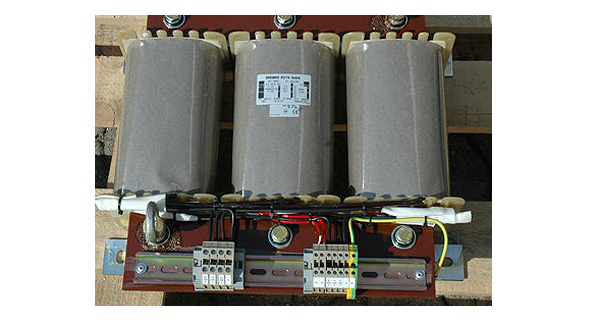
For a three phase transformer, three primary windings are connected together and three secondary windings are connected together.
A single three phase transformer is preferred to three single phase transformers so as to get good efficiency, where it occupies less space at low cost. But due to the transportation problem of heavy equipment, single phase transformers are used in most cases.
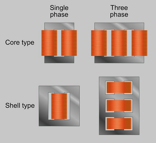
Another classification of these transformers is Core and Shell type.
-
In Shell type, the windings are positioned on a single leg surrounded by the core.
-
In Core type, they are wounded on different legs.
The difference is well known by having a look at the following figure.
The classification of transformers can also be done depending upon the type of core material used. These are actually RF transformers, which contain many types such as Air-core transformers, Ferrite core transformers, Transmission line transformers and Balun transformers. Balun transformers are used in RF receiver systems. The main types are the air core and iron core transformers.
Air-core Transformer
This is a core type transformer in which the windings are wound on a non-magnetic strip. The magnetic flux linkages are made through air as core between the primary and secondary. The following image shows an air-core transformer.
Advantages
- The hysteresis and eddy current losses are low in these Air core transformers.
- Noise production is low.
Disadvantages
- The reluctance is high in Air core transformers.
- Mutual inductance is low in Air core compared to Iron-core transformers.
Applications
- Audio frequency transformers.
- High frequency radio transmissions.
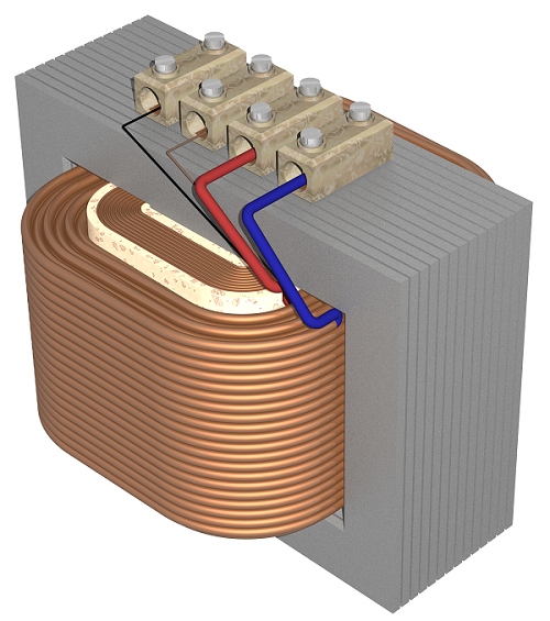
Iron Core Transformers
This is a core type transformer in which the windings are wound on an iron core. The magnetic flux linkages are made strong and perfect with iron as core material. This is commonly seen in laboratories. The figure below shows an example of iron core transformer.
Advantages
- They have very high magnetic permeability.
- Iron core transformers has low reluctance.
- Mutual Inductance is high.
- These transformers are highly efficient.
Disadvantages
- These are a bit noisy compared to Air core transformers.
- The hysteresis and eddy current losses are a bit more than Air core transformers.
Applications
- As isolation transformers.
- High frequency radio transmissions.
The transformers are also classified according to the type of core they use. Some transformers use the core immersed in oil. This oil is cooled from outside by various methods. Such transformers are named as Wet core transformers, while the others such as ferrite core transformers, laminated core transformers, toroidal core transformers and cast resin transformers are Dry core transformers.
Based on the type of winding technique, we have another transformer which is very popular named as the Auto transformer.
Auto Transformer
This is type of transformer which is mostly seen in our electrical laboratories. This auto transformer is an improved version of the original transformer. A single winding is taken to which both the sides are connected to power and the ground. Another variable tapping is made by whose movement secondary of the transformer is formed.
The following figure shows the circuit of an auto-transformer.
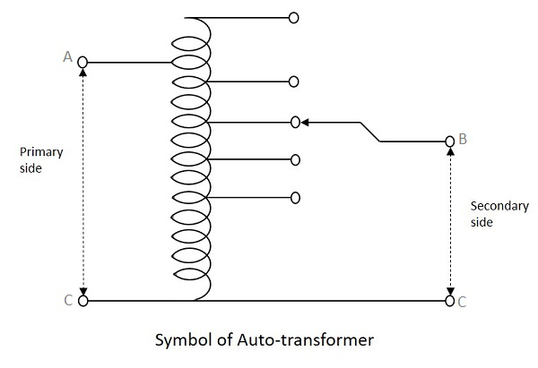
As shown in the figure, a single winding provides both primary and secondary in a transformer. Various tapping of secondary winding are drawn to select various voltage levels at the secondary side.
The primary winding as shown above is from A to C and the secondary winding is from B to C whereas the variable arm B is varied to get the required voltage levels. A practical auto transformer looks like the figure below.
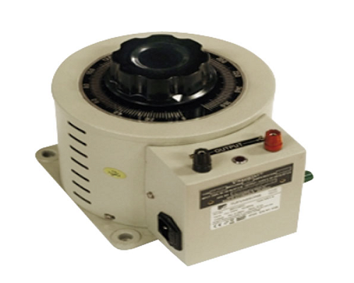
By rotating the shaft above, the secondary voltage is adjusted to different voltage levels. If the voltage applied across the points A and C is V1, then the voltage per turn in this winding will be
Voltageperturn=V1N1??????????????=?1?1
Now, the voltage across the points B and C will be
V2=V1N1×N2?2=?1?1×?2
V2V1=N2N1=constant(sayK)?2?1=?2?1=????????(????)
This constant is nothing but the turns ratio or voltage ratio of the auto transformer.
Frequently Asked Questions
Recommended Posts:
- Basic Electronics Tutorial
- Basic Electronics - Materials
- Basic Electronics - Energy Bands
- Basic Electronics - Semiconductors
- Basic Electronics - Hall Effect
- Basic Electronics - Resistors
- Circuit Connections in Resistors
- Basic Electronics - Non linear Resistors
- Basic Electronics - Linear Resistors
- Basic Electronics - Fixed Resistors
- Basic Electronics - Capacitors
- Circuit Connections in Capacitors
- Basic Electronics - Variable Capacitors
- Basic Electronics - Fixed Capacitors
- Basic Electronics - Polarized Capacitors