ER Diagram Representation
ER Diagram Representation
Let us now learn how the ER Model is represented by means of an ER diagram. Any object, for example, entities, attributes of an entity, relationship sets, and attributes of relationship sets, can be represented with the help of an ER diagram.
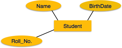
Entity
Entities are represented by means of rectangles. Rectangles are named with the entity set they represent.

Attributes
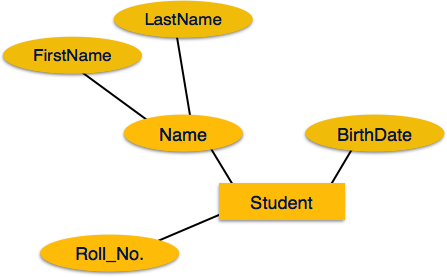
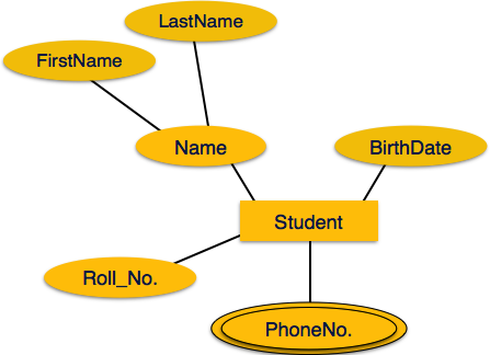
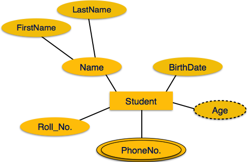
Attributes are the properties of entities. Attributes are represented by means of ellipses. Every ellipse represents one attribute and is directly connected to its entity (rectangle).
If the attributes are composite, they are further divided in a tree like structure. Every node is then connected to its attribute. That is, composite attributes are represented by ellipses that are connected with an ellipse.
Multivalued attributes are depicted by double ellipse.
Derived attributes are depicted by dashed ellipse.
Relationship
Relationships are represented by diamond-shaped box. Name of the relationship is written inside the diamond-box. All the entities (rectangles) participating in a relationship, are connected to it by a line.
Binary Relationship and Cardinality
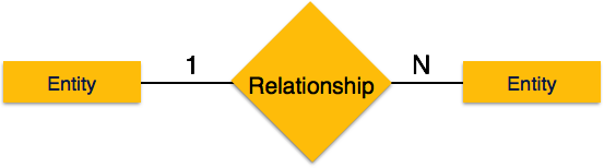
A relationship where two entities are participating is called a binary relationship. Cardinality is the number of instance of an entity from a relation that can be associated with the relation.

-
One-to-one − When only one instance of an entity is associated with the relationship, it is marked as '1:1'. The following image reflects that only one instance of each entity should be associated with the relationship. It depicts one-to-one relationship.
-
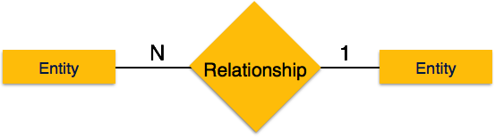
One-to-many − When more than one instance of an entity is associated with a relationship, it is marked as '1:N'. The following image reflects that only one instance of entity on the left and more than one instance of an entity on the right can be associated with the relationship. It depicts one-to-many relationship.
-
Many-to-one − When more than one instance of entity is associated with the relationship, it is marked as 'N:1'. The following image reflects that more than one instance of an entity on the left and only one instance of an entity on the right can be associated with the relationship. It depicts many-to-one relationship.
-
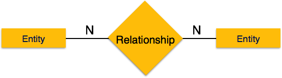
Many-to-many − The following image reflects that more than one instance of an entity on the left and more than one instance of an entity on the right can be associated with the relationship. It depicts many-to-many relationship.
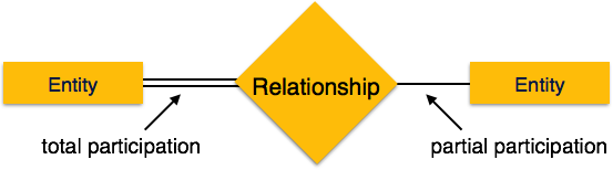
Participation Constraints
-
Total Participation − Each entity is involved in the relationship. Total participation is represented by double lines.
-
Partial participation − Not all entities are involved in the relationship. Partial participation is represented by single lines.