Digital Circuits - Two-Level Logic Realization
Digital Circuits - Two-Level Logic Realization
The maximum number of levels that are present between inputs and output is two in two level logic. That means, irrespective of total number of logic gates, the maximum number of Logic gates that are present cascaded???????? between any input and output is two in two level logic. Here, the outputs of first level Logic gates are connected as inputs of second level Logic gates?.
Consider the four Logic gates AND, OR, NAND & NOR. Since, there are 4 Logic gates, we will get 16 possible ways of realizing two level logic. Those are AND-AND, AND-OR, ANDNAND, AND-NOR, OR-AND, OR-OR, OR-NAND, OR-NOR, NAND-AND, NAND-OR, NANDNAND, NAND-NOR, NOR-AND, NOR-OR, NOR-NAND, NOR-NOR.
These two level logic realizations can be classified into the following two categories.
- Degenerative form
- Non-degenerative form
Degenerative Form
If the output of two level logic realization can be obtained by using single Logic gate, then it is called as degenerative form. Obviously, the number of inputs of single Logic gate increases. Due to this, the fan-in of Logic gate increases. This is an advantage of degenerative form.
Only 6 combinations of two level logic realizations out of 16 combinations come under degenerative form. Those are AND-AND, AND-NAND, OR-OR, OR-NOR, NAND-NOR, NORNAND.
In this section, let us discuss some realizations. Assume, A, B, C & D are the inputs and Y is the output in each logic realization.
AND-AND Logic
In this logic realization, AND gates are present in both levels. Below figure shows an example for AND-AND logic realization.
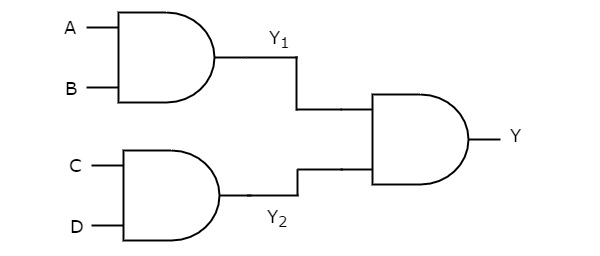
We will get the outputs of first level logic gates as Y1=AB?1=?? and Y2=CD?2=??
These outputs, Y1?1 and Y2?2 are applied as inputs of AND gate that is present in second level. So, the output of this AND gate is
Y=Y1Y2?=?1?2
Substitute Y1?1 and Y2?2 values in the above equation.
Y=(AB)(CD)?=(??)(??)
⇒Y=ABCD⇒?=????
Therefore, the output of this AND-AND logic realization is ABCD. This Boolean function can be implemented by using a 4 input AND gate. Hence, it is degenerative form.
AND-NAND Logic
In this logic realization, AND gates are present in first level and NAND gates? are present in second level. The following figure shows an example for AND-NAND logic realization.
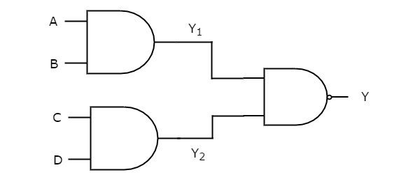
Previously, we got the outputs of first level logic gates as Y1=AB?1=?? and Y2=CD?2=??
These outputs,Y1?1 and Y2?2 are applied as inputs of NAND gate that is present in second level. So, the output of this NAND gate is
Y=(Y1Y2)′?=(?1?2)′
Substitute Y1?1 and Y2?2 values in the above equation.
Y=((AB)(CD))′?=((??)(??))′
⇒Y=(ABCD)′⇒?=(????)′
Therefore, the output of this AND-NAND logic realization is (ABCD)′(????)′. This Boolean function can be implemented by using a 4 input NAND gate. Hence, it is degenerative form.
OR-OR Logic
In this logic realization, OR gates are present in both levels. The following figure shows an example for OR-OR logic realization.
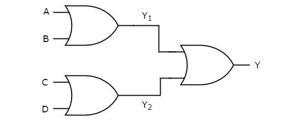
We will get the outputs of first level logic gates as Y1=A+B?1=?+? and Y2=C+D?2=?+?.
These outputs, Y1?1 and Y2?2 are applied as inputs of OR gate that is present in second level. So, the output of this OR gate is
Y=Y1+Y2?=?1+?2
Substitute Y1?1 and Y2?2 values in the above equation.
Y=(A+B)+(C+D)?=(?+?)+(?+?)
⇒Y=A+B+C+D⇒?=?+?+?+?
Therefore, the output of this OR-OR logic realization is A+B+C+D. This Boolean function can be implemented by using a 4 input OR gate. Hence, it is degenerative form.
Similarly, you can verify whether the remaining realizations belong to this category or not.
Non-degenerative Form
If the output of two level logic realization can’t be obtained by using single logic gate, then it is called as non-degenerative form.
The remaining 10 combinations of two level logic realizations come under nondegenerative form. Those are AND-OR, AND-NOR, OR-AND, OR-NAND, NAND-AND, NANDOR, NAND-NAND, NOR-AND, NOR-OR, NOR-NOR.
Now, let us discuss some realizations. Assume, A, B, C & D are the inputs and Y is the output in each logic realization.
AND-OR Logic
In this logic realization, AND gates are present in first level and OR gates? are present in second level. Below figure shows an example for AND-OR logic realization.
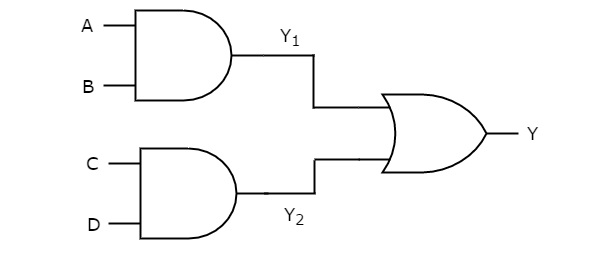
Previously, we got the outputs of first level logic gates as Y1=AB?1=?? and Y2=CD?2=??.
These outputs, Y1 and Y2 are applied as inputs of OR gate that is present in second level. So, the output of this OR gate is
Y=Y1+Y2?=?1+?2
Substitute Y1?1 and Y2?2 values in the above equation
Y=AB+CD?=??+??
Therefore, the output of this AND-OR logic realization is AB+CD. This Boolean function is in Sum of Products form. Since, we can’t implement it by using single logic gate, this AND-OR logic realization is a non-degenerative form.
AND-NOR Logic
In this logic realization, AND gates are present in first level and NOR gates? are present in second level. The following figure shows an example for AND-NOR logic realization.
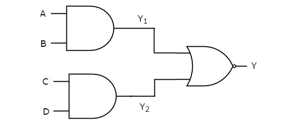
We know the outputs of first level logic gates as Y1=AB?1=?? and Y2=CD?2=??
These outputs, Y1 and Y2 are applied as inputs of NOR gate that is present in second level. So, the output of this NOR gate is
Y=(Y1+Y2)′?=(?1+?2)′
Substitute Y1?1 and Y2?2 values in the above equation.
Y=(AB+CD)′?=(??+??)′
Therefore, the output of this AND-NOR logic realization is (AB+CD)′(??+??)′. This Boolean function is in AND-OR-Invert form. Since, we can’t implement it by using single logic gate, this AND-NOR logic realization is a non-degenerative form
OR-AND Logic
In this logic realization, OR gates are present in first level & AND gates? are present in second level. The following figure shows an example for OR-AND logic realization.
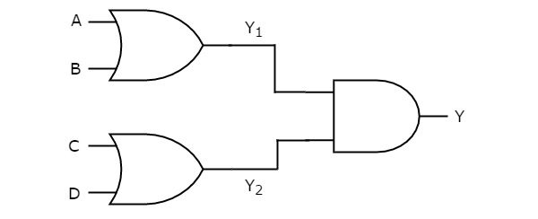
Previously, we got the outputs of first level logic gates as Y1=A+B?1=?+? and Y2=C+D?2=?+?.
These outputs, Y1?1 and Y2?2 are applied as inputs of AND gate that is present in second level. So, the output of this AND gate is
Y=Y1Y2?=?1?2
Substitute Y1?1 and Y2?2 values in the above equation.
Y=(A+B)(C+D)?=(?+?)(?+?)
Therefore, the output of this OR-AND logic realization is A+B?+? C+D?+?. This Boolean function is in Product of Sums form. Since, we can’t implement it by using single logic gate, this OR-AND logic realization is a non-degenerative form.
Similarly, you can verify whether the remaining realizations belong to this category or not.