Digital Circuits - Finite State Machines
Digital Circuits - Finite State Machines
We know that synchronous sequential circuits change affect?????? their states for every positive ornegative?????????? transition of the clock signal based on the input. So, this behavior of synchronous sequential circuits can be represented in the graphical form and it is known as state diagram.
A synchronous sequential circuit is also called as Finite State Machine FSM???, if it has finite number of states. There are two types of FSMs.
- Mealy State Machine
- Moore State Machine
Now, let us discuss about these two state machines one by one.
Mealy State Machine
A Finite State Machine is said to be Mealy state machine, if outputs depend on both present inputs & present states. The block diagram of Mealy state machine is shown in the following figure.
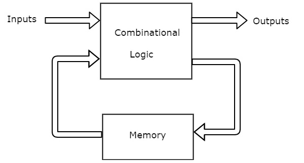
As shown in figure, there are two parts present in Mealy state machine. Those are combinational logic and memory. Memory is useful to provide some or part of previous outputs presentstates????????????? as inputs of combinational logic.
So, based on the present inputs and present states, the Mealy state machine produces outputs. Therefore, the outputs will be valid only at positive ornegative?????????? transition of the clock signal.
The state diagram of Mealy state machine is shown in the following figure.
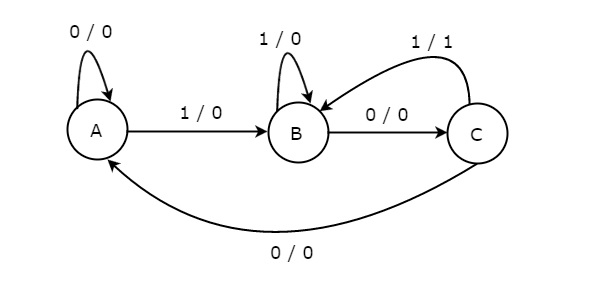
In the above figure, there are three states, namely A, B & C. These states are labelled inside the circles & each circle corresponds to one state. Transitions between these states are represented with directed lines. Here, 0 / 0, 1 / 0 & 1 / 1 denotes input / output. In the above figure, there are two transitions from each state based on the value of input, x.
In general, the number of states required in Mealy state machine is less than or equal to the number of states required in Moore state machine. There is an equivalent Moore state machine for each Mealy state machine.
Moore State Machine
A Finite State Machine is said to be Moore state machine, if outputs depend only on present states. The block diagram of Moore state machine is shown in the following figure.
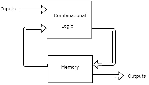
As shown in figure, there are two parts present in Moore state machine. Those are combinational logic and memory. In this case, the present inputs and present states determine the next states. So, based on next states, Moore state machine produces the outputs. Therefore, the outputs will be valid only after transition of the state.
The state diagram of Moore state machine is shown in the following figure.
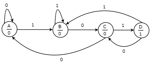
In the above figure, there are four states, namely A, B, C & D. These states and the respective outputs are labelled inside the circles. Here, only the input value is labeled on each transition. In the above figure, there are two transitions from each state based on the value of input, x.
In general, the number of states required in Moore state machine is more than or equal to the number of states required in Mealy state machine. There is an equivalent Mealy state machine for each Moore state machine. So, based on the requirement we can use one of them.
Frequently Asked Questions
Recommended Posts:
- Digital Circuits Tutorial
- Digital Circuits - Number Systems
- Digital Circuits - Signed Binary Arithmetic
- Digital Circuits - Codes
- Error Detection & Correction Codes
- Digital Circuits - Boolean Algebra
- Digital Circuits - Canonical & Standard Forms
- Digital Circuits - K-Map Method
- Quine-McCluskey Tabular Method
- Digital Circuits - Logic Gates
- Digital Circuits - Two-Level Logic Realization
- Digital Combinational Circuits
- Digital Circuits - Decoders
- Digital Circuits - Encoders
- Digital Circuits - Encoders