Digital Circuits - Algorithmic State Machines
Digital Circuits - Algorithmic State Machines
Every digital system can be partitioned into two parts. Those are data path digital??????? circuits and control circuits. Data path circuits perform the functions such as storing of binary information data???? and transfer of data from one system to the other system. Whereas, control circuits determine the flow of operations of digital circuits.
It is difficult to describe the behavior of large state machines using state diagrams. To overcome this difficulty, Algorithmic State Machine ASM??? charts can be used. ASM charts are similar to flow charts. They are used to represent the flow of tasks to be performed by data path circuits and control circuits.
Basic Components of ASM charts
Following are the three basic components of ASM charts.
- State box
- Decision box
- Conditional output box
State box
State box is represented in rectangular shape. Each state box represents one state of the sequential circuit. The symbol of state box is shown in the following figure.
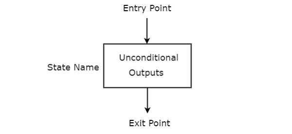
It is having one entry point and one exit point. Name of the state is placed to the left of state box. The unconditional outputs corresponding to that state can be placed inside state box. Moore state machine outputs can also be placed inside state box.
Decision box
Decision box is represented in diamond shape. The symbol of decision box is shown in the following figure.
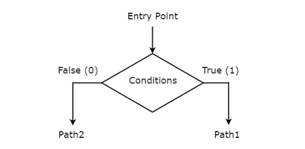
It is having one entry point and two exit paths. The inputs or Boolean expressions can be placed inside the decision box, which are to be checked whether they are true or false. If the condition is true, then it will prefer path1. Otherwise, it will prefer path2.
Conditional output box
Conditional output box is represented in oval shape. The symbol of conditional output box is shown in the following figure.
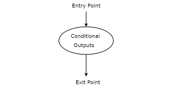
It is also having one entry point and one exit point similar to state box. The conditional outputs can be placed inside state box. In general, Mealy state machine outputs are represented inside conditional output box. So, based on the requirement, we can use the above components properly for drawing ASM charts.
Frequently Asked Questions
Recommended Posts:
- Digital Circuits Tutorial
- Digital Circuits - Number Systems
- Digital Circuits - Signed Binary Arithmetic
- Digital Circuits - Codes
- Error Detection & Correction Codes
- Digital Circuits - Boolean Algebra
- Digital Circuits - Canonical & Standard Forms
- Digital Circuits - K-Map Method
- Quine-McCluskey Tabular Method
- Digital Circuits - Logic Gates
- Digital Circuits - Two-Level Logic Realization
- Digital Combinational Circuits
- Digital Circuits - Decoders
- Digital Circuits - Encoders
- Digital Circuits - Encoders